


You Passed, Now What? Steps to Take After Earning Your HAM Radio License
You Passed, Now What? Steps to Take After Earning Your HAM Radio License
Amateur (aka HAM) Radio has proven time and again to be an invaluable option when existing communication infrastructure fails due to natural or man-made disasters. This article is the beginning of a series of four articles providing guidance on what to do after earning your HAM Radio license.
This series will include tips on selecting and configuring equipment, creating a communications plan, building a communications “go-bag” and running periodic communications-oriented drills to build and maintain your skills on the air. Let’s get started!
Select the Right Equipment
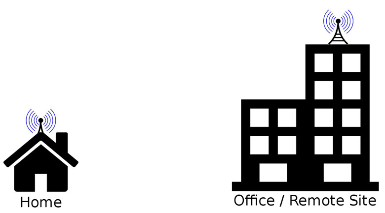
Congratulations on earning your HAM Radio license! This article deals with choosing your radio and support equipment and in order to do that, we need to define the purpose and objective for your use of HAM Radio. For this series, we’re going to focus on emergency communication between two fixed base stations. An example of this would be communication between two homes or between your home and your office.
We’ll also assume that these two stations are located no further than 25 miles from each other, which will allow us to use either VHF/UHF simplex or a VHF/UHF repeater network, depending on the distance and terrain. Future articles may cover amateur mobile (i.e. vehicle-based) or portable (i.e. on foot) operation.
Step 1: Choosing Your Radio
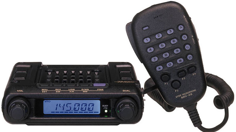
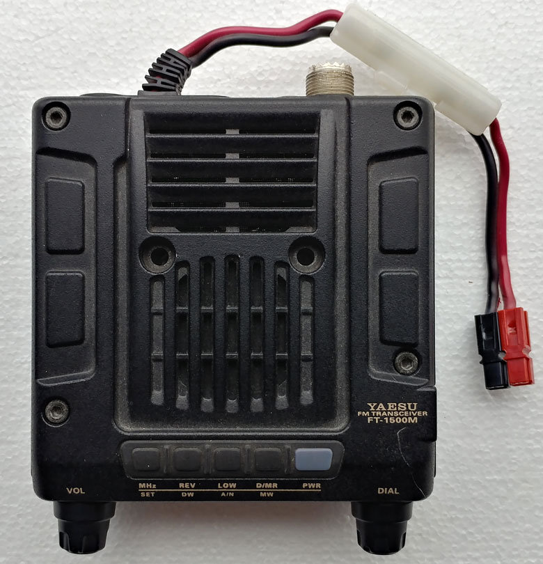
The Author’s Yaesu FT-1500M – A Simple and Rugged 2m Transceiver
Given the above scenario, we need a VHF transceiver that (1) covers the 2 meter (144 – 148 Mhz) band, (2) uses 12V DC power (to allow battery-powered operation under emergency conditions), (3) has an RF output power of at least 50W, (4) is simple to operate, (5) is made by a proven and reputable manufacturer and (6) is relatively inexpensive. Coverage of the 70 cm (420 – 450 Mhz) band is optional, as it offers greater communication options at the expense of increased operating complexity and unit cost.
We’ll specifically exclude all handheld (HT) radios from our list. As cool as an HT can be, they’re under-powered, expensive and more complex to operate. We’ll also exclude transceivers with digital HAM Radio (e.g. D-Star) capabilities due to high cost, high complexity and inadequate digital repeater coverage.
So what are our choices? Basically, most VHF mobile transceivers from Yaesu, ICOM and Kenwood. My personal choice is the venerable Yaesu FT-1500M which meets all of the above requirements in a rugged, fan-less design (the entire case is an aluminum heat sink). While the FT-1500M isn’t in production anymore, any of the following current production radios would be a good choice:
| Brand | Model | Price | Band | RF Output |
|---|---|---|---|---|
| Yaesu | FT-2980R | $199 | 2m | 80 Watts |
| ICOM | IC-2300H | $205 | 2m | 65 Watts |
| Kenwood | TM-281A | $145 | 2m | 65 Watts |
Step 2: Selecting an Antenna
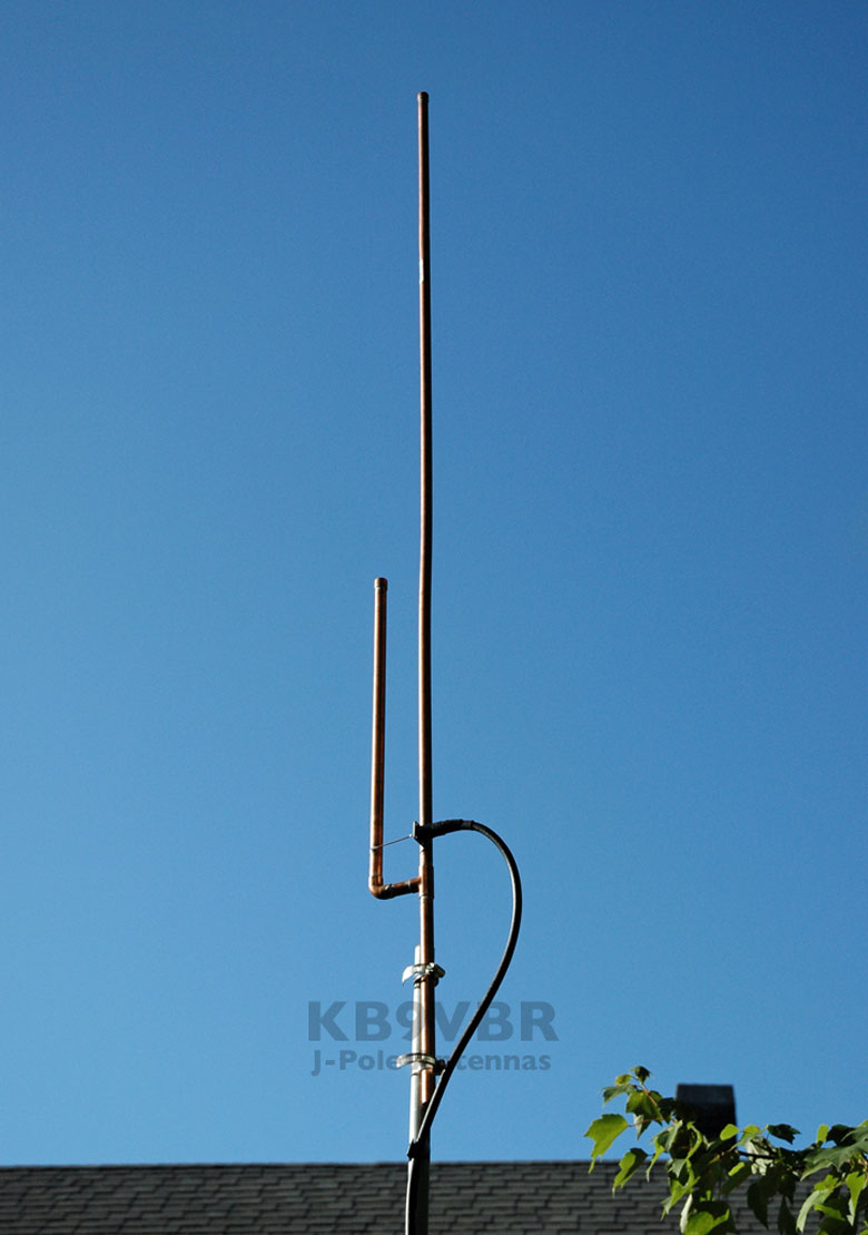
The KB9VBR J-Pole Antenna
Radio wave propagation is a factor of (1) operating frequency, where lower frequencies generally provide greater range and higher frequencies provide superior data transfer rates, (2) antenna design, (3) environmental conditions, such as intervening terrain and atmospheric ionization and (4) transmitter power. To a certain degree, the operating mode will also impact the perceived propagation with digital modes generally being an all-or-nothing affair and primitive analog modes like morse code (CW) being effective even during a raging electrical storm.
Considering all of the above factors, the most important element in a radio circuit is the antenna. You may have a powerful transmitter broadcasting on an optimal frequency, but without the correct antenna, communication will be suboptimal, if not impossible.
There are a multitude of antenna configurations to choose from, even for short-range VHF/UHF communication, but they can generally be divided into two categories; directional and omnidirectional. For our scenario, installing a directional antenna at each base station would be very effective for direct simplex communication, but would limit our use of repeaters to only those in alignment with each antenna. For this reason, a general-purpose omnidirectional antenna is a more flexible choice.
Our omnidirectional antenna should be (1) efficient, like one with a Standing Wave Ratio (SWR) less than 1.5:1 across the entire 2 meter band (144 – 148 Mhz) and possessing a positive gain over the reference dipole, (2) rugged enough to be mounted outside and withstand all weather conditions, (3) capable of handling the full RF output power of the transceiver, (4) inexpensive, but made from high-quality components and (5) relatively easy to install, requiring neither a large ground plane nor an extensive network of radials.
The best answer is a J-pole antenna made from 1/2 inch diameter copper pipe soldered together and sturdily mounted to a mast, which is then bolted to the exterior of each station as shown in the photo above.
While building a “copper cactus” J-pole antenna is a time-honored rite of passage for many HAM Radio operators, KB9VBR sells fully-assembled and tuned antennas ready-to-go right out of the box for $34. KB9VBR also offers a take-down J-pole which could be stored at the office or a remote location if permanent installation isn’t an option.
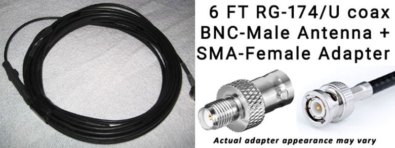
The KB3KAI Roll-up J-Pole Antenna
An alternative choice, particularly for apartment-dwellers or the office location is a roll-up J-pole. Typically made from 300 ohm balanced line twin lead, these antennas offer similar performance to the copper cactus, but are only capable of handling 50 watts of RF power. KB3KAI sells a roll-up J-pole with a PL-259 adapater and 12ft of RG58A/U coax for $40, which would be a good choice for any of the radios (on low and medium power settings) described in first step above.
Deployment of a roll-up J-pole consists of hanging the top of the antenna from an interior wall, door, hook, etc., ensuring that the antenna hangs vertically and then running the coax to the radio.
Step 3: Choosing A Power Source
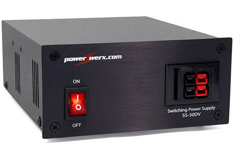
Powerwerx SS-30DV
A typical LTE smartphone radiates 0.2 watts of RF power and draws less than 1A of current. The HAM Radios highlighted above can generate 250 (50W) to 400 (80W) times more RF power and will draw up to 15A of current at 12V DC. While all of the HAM Radios selected above have adjustable power settings (typically 5/10/25 max watts) with correspondingly lower current requirements, we’re still going to need a much more substantial power source than your average consumer electronics device.
For normal operation, a small switching power supply plugged into a wall outlet is the ideal choice. The Powerwerx model SS-30DV is rated to 25A continuous output and is a great choice for any of the radios discussed above.
Emergency operation is slightly more problematic as it requires some form of battery and a charging system. If cost isn’t an option, the Goal Zero Yeti 1400 Lithium would be ideal, although the Yeti 1250 is also a good choice. Both have more than 100Ah of storage and can handle current loads of 33A via a set of Anderson Powerpole connectors.
Realistically though, cost is a concern for most people. Furthermore, as HAM Radio operators, we’re required by law to operate at the minimum power necessary to establish contact and as a practical matter, we need to preserve battery power as much as possible in an emergency. Therefore, even though our radios may be capable of transmitting at over 50W, we should be operating below 10W the vast majority of the time.
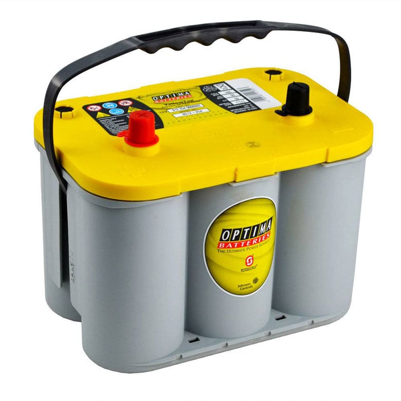
Optima Yellowtop AGM Battery
With careful power management, a simple automotive battery is a good choice, especially a deep-cycle sealed Absorbed Glass Mat (AGM) battery like an OPTIMA Model D35 Yellow Top.
With 48Ah of capacity, the OPTIMA is capable of running a station for several days, assuming a transmit power of <10W (i.e. ~6A current draw) and a typical 20% transmit-to-receive duty cycle.
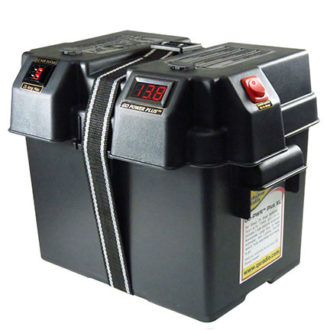
The battery should be enclosed in an acid-resistant, non-conductive container, such as a Go-PWR Plus Battery Box, which conveniently also includes a wiring harness, dual Powerpole connectors, a voltmeter and a power switch.
You can’t use a switching power supply for battery charging, as it will overcharge and damage the battery, so we’re going to need a dedicated battery charger that can not only charge the battery but also hold it in a charged state indefinitely. The Battery Tender 022-0186G-DL-WH Power Tender Plus Battery Charger/Maintainer is a good choice for this task.
If you’re uncomfortable with installing or configuring a battery backup power source for your station, at least buy (or fabricate) the cabling necessary to connect your radio to an automotive battery and store it at each station. That way, in an emergency, all you’ll need to do is pull a battery from a car to get on the air.
Step 4: Install A Powerpole Connector (Optional)
In the last section, we made reference to the Anderson Powerpole connector for supplying our radios with electrical power. Powerpoles are the standard power connector used by the Amateur Radio Emergency Service (ARES) and the Radio Amateur Civil Emergency Service (RACES) throughout the United States. Unfortunately, due to the cost of the connectors, radio manufacturers still ship their products with Molex-style connectors in a wide variety of configurations, making interoperability of radios and power sources an issue.
We’re going to fix that by removing the power connectors on each radio (you did buy a radio for each station, right?) and replacing them with Anderson Powerpoles. The end product should look like the photo above.
The Powerpoles are the red and black connectors at the end of the power cord. Notice the fuse holder installed on the positive wire. We want to make sure not to compromise the fuse protecting your radio, so it’s important to cut the power cord as close as possible to the OEM power connector.
Powerwerx offers a full line of Powerpole connectors, housings and tools. While detailed instructions on installing Powerpole connectors are beyond the scope of this article, instructions and videos can be found online. The Amateur Radio Relay League (ARRL) actually provides a step-by-step procedure for installation.
A few comments on the ARRL instructions:
- Powerpoles are polarized connectors; however, the plastic connector housings must be assembled in the correct orientation, as defined by the ARES/RACES standard. The easiest way to do this is to test fit your housings in a commercial Powerpole connector, like the one on the Powerwerx SS-30DV power supply. If they go in and red matches to red and black matches to black, you’re good.
- Do not use the roll pin to secure the connector housings. Use Superglue instead. However, make sure you’ve checked the orientation before gluing!
- Do spend the money to buy a dedicated Powerpole crimper.
- Do make sure that the connector orientation matches the housing orientation BEFORE you crimp the connectors (ask me how I know this).
- Do use the 30A Powerpole connectors for 12 and 14 gauge wire and the 15A connectors for smaller gauge wire (the housings will be the same though).
- Do not bother trying to solder the connectors. The crimp connection will work just fine.
- Do retro-fit Powerpoles to all of your DC equipment, including battery chargers, wiring harnesses, etc.
That’s it!
With a radio, antenna and power supply, you’re now ready to get on the air! In the next article, we’ll discuss mapping the local repeater network in your area and setting up a communications plan between your two stations.
Editor’s Note: We’d like to welcome Scott Drumm as a contributor here on ITS! Scott’s a wealth of knowledge when it comes to HAM Radio and you might meet him on the airwaves under his callsign, N3XFD.
Discussion