


How to Build a Robust Bumper for CJ-Series Jeeps
How to Build a Robust Bumper for CJ-Series Jeeps
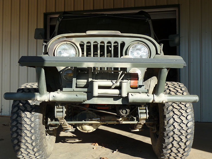
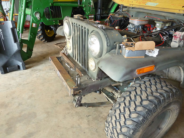
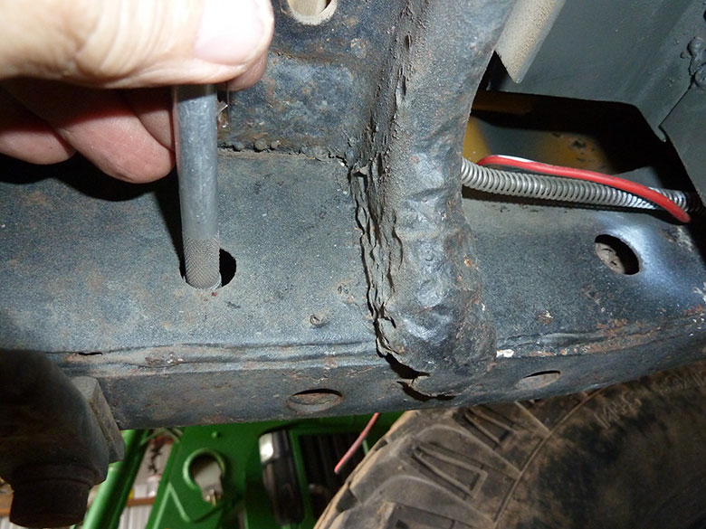
Everyone has seen an old Jeep with a mangled front bumper that’s a result from pushing or an accident. My old CJ5 was one of those. Many CJ-Series Jeeps have winches of varying capacities that are often bolted to the 1/8″ thick metal between the radiator grill and bumper. Others may be mounted to a large piece of “C” channel (ostensibly designed to mount a winch) and the whole affair is then bolted through that thin tack-welded piece of metal between the bumper and grill.
Some Jeep owners install winches because of their “tough look” with no intention of ever seriously taking their vehicle off-road, but whatever the intent, winches and winch mounts bolted to the thin metal between the bumper and grill can fail under load with damaging results. Several articles previously posted by others on ITS discuss the use of winches and the poor mounting options available from winch vendors. I’m certain that if you take a Jeep into rough terrain or into the water often enough, it will eventually get stuck. Having a winch equipped vehicle can ease your way out of a rough spot.
Building a Robust Bumper
The genesis of the project I’m discussing today was discovering an unused winch I’d stored in a CONEX box years earlier. It had originally been intended for a new 4×4 Ford one-ton truck with a V10 engine. That vehicle was soon traded due to poor gas mileage and thus the winch sat unused. Along with the winch was a typical 1/4″ thick “C” type universal winch mounting plate.
This article will discuss the general fabrication of a robust front bumper with winch mount that’s easily adapted to any CJ-Series Jeep. This bumper/winch mount is fully capable of taking the strain of a 10,000 pound pull winch. The project took about two full days to complete using common shop equipment including a stick arc welder, chop saw and reciprocating sawzall.
The project used four vertical bolts and four horizontal bolts, all passing through the frame rails and two bolts passing through the front “C” channel bumper assembly and frame rails to secure the fabricated bumper assembly to the Jeep. The winch mounting plate was secured to the bumper by two bolts through each side rail, four bolts through the front bumper and two bolts through the thin metal located between the radiator and bumper. In addition, the rear of the winch mount was tack welded to the bumper side plates which provided greatly increased rigidity for the front frame rails. Grade 6 bolts and hardware were used throughout this project. (Grade 8 bolts are harder but more brittle).
Designing the Bumper
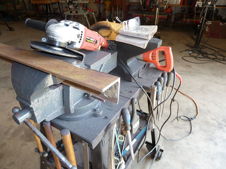
During project design, I looked around my scrap metal pile for suitable materials, extracting various lengths of three and four-inch angle iron, 2 3/8 and 2 7/8 inch diameter drill tubing (the smaller slips nicely inside the larger) and a length of three-inch “C” channel. The existing front bumper was removed and the distance between the outside edges of the front frame rails was measured. Suitable lengths of both three and four-inch angle iron were cut with a chop saw. Sharp ends resulting from these and all subsequent cuts were rounded with an angle grinder.
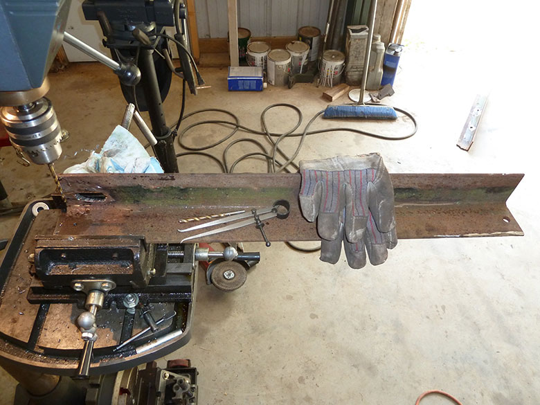
The three and four-inch angle iron slipped nicely together, forming a reinforced C shape that fits over the ends of the front frame rails. Existing upper and lower holes in the front end of the frame rails were marked on the angle iron for subsequent drilling. A cross slide vise and drill press made for easy bolt hole alignment and drilling.
Building the Bumper
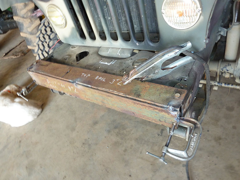
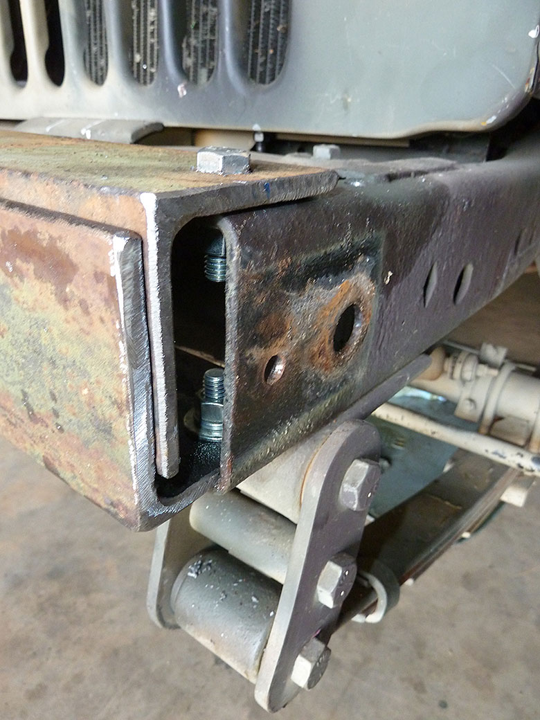
After both pieces of angle iron were drilled, a 3/8 x 4 ½ bolt was passed from the holes in the top 3” angle iron, through the frame rails into the nesting bottom 4” angle iron. Two bolts were used temporarily to mount the angle iron to the frame until the right Grade 6 bolts could be procured. The frame rail bolts were slightly tightened and angle iron ends clamped together for tack welding. This front bumper assembly will eventually be continually welded on both the inside and outside, resulting in a rigid “C” shape.
Two pieces of 4 inch angle iron were cut to extend from the “C” assembly over the frame rails, to the radiator grill. These pieces were carefully cut using a sawzall, then assembled and clamped in position for tack welding.
The two side plates were then tacked to the “C” shaped front bumper. As the winch will be offset slightly from the centerline, a piece cut from the frame rails was welded to the top of the right rail side plate. The winch mounting bracket was positioned on top of this assembly in final position and winch mounting holes were marked and tapped. Existing horizontal holes in the frame rail were marked on the two side rails.
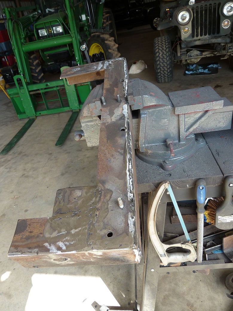
This assembly was then removed and both angle iron and the side plates were continuously welded inside and outside. Three bolts are visible extending from the underside of the bumper/winch mount assembly. These bolts were threaded into tapped holes to ensure the threads were cut properly and were subsequently removed. Two recesses were countersunk into the top 3-inch angle iron rail of the bumper in order to accommodate the two front bolts for the winch.
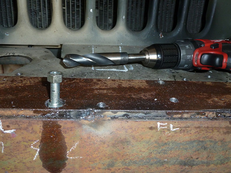
Due to the tight fit between the mounting rail and winch, the rear two winch-mounting bolts were passed through the rail and the existing thin piece of metal extending from the bumper to the frame rail. For rigidity, the winch will rely on the mounting plate being bolted to the fabricated bumper in numerous places and tack welded to the reinforced bumper side arms.
The winch mounting plate was next mated to the bumper. A ratcheting tap wrench was used to cut some bolt holes fastening the winch mount to the bumper and frame rails. Wherever possible, tapped holes were backed up with flat washers, lock washers and nuts.

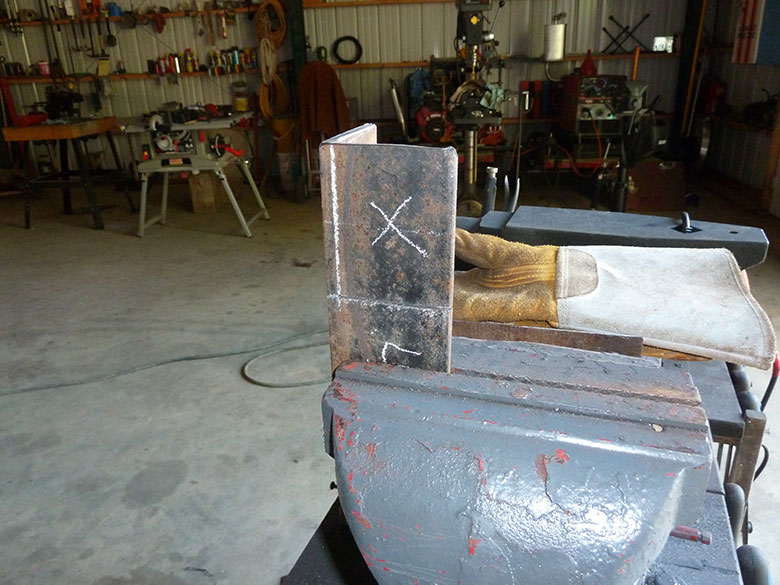
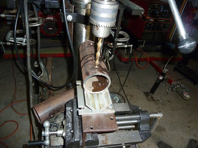
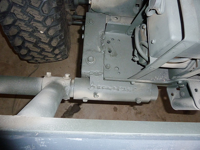
Two pieces of 2 7/8” drill tubing were cut and drilled to accept the two 3/8” bumper pipe mounting bolts and grease zerks. A “V” block was used in the cross slide vise to ensure all holes drilled passed through the geometric center of the tubing. Additionally, the hole for the grease zerk was threaded. The other two holes shown in the above photo were used to secure the 2 3/8” pipe to the larger sized drill tubing.
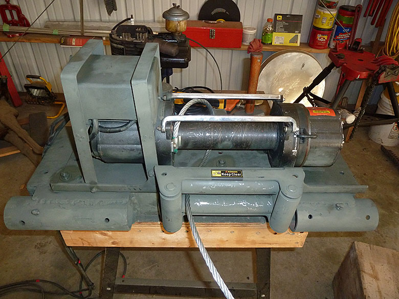
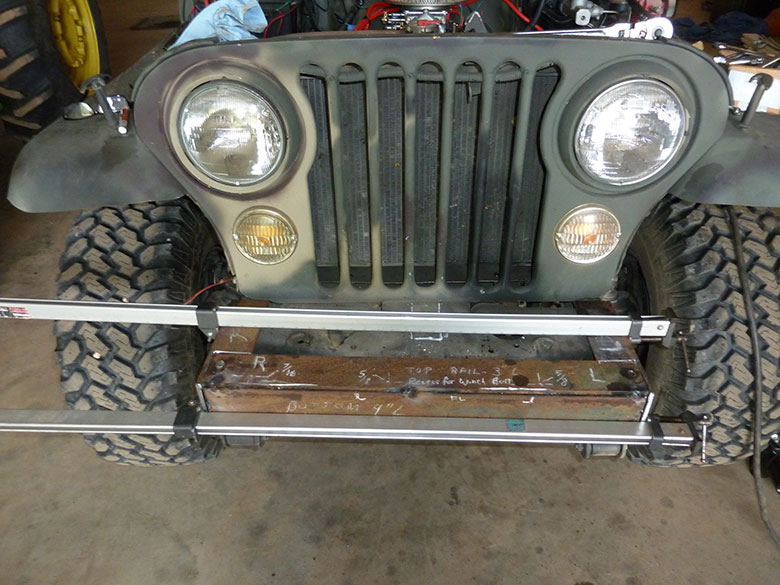
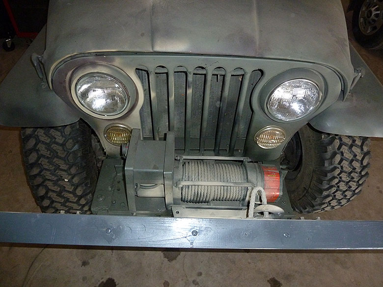
Two pieces of “C” rail were cut and welded onto both sides of the front of the bumper assembly. This rail forms a perfect nest for the 2 7/8” horizontal bumper mount that was in turn welded to the edges of the “C” rail. The winch and winch plate was then bolted onto the bumper assembly. The winch cable was unspooled and last ten feet of cable to the capstan were painted red. Red cable serves as an alert that no more cable should be run out.
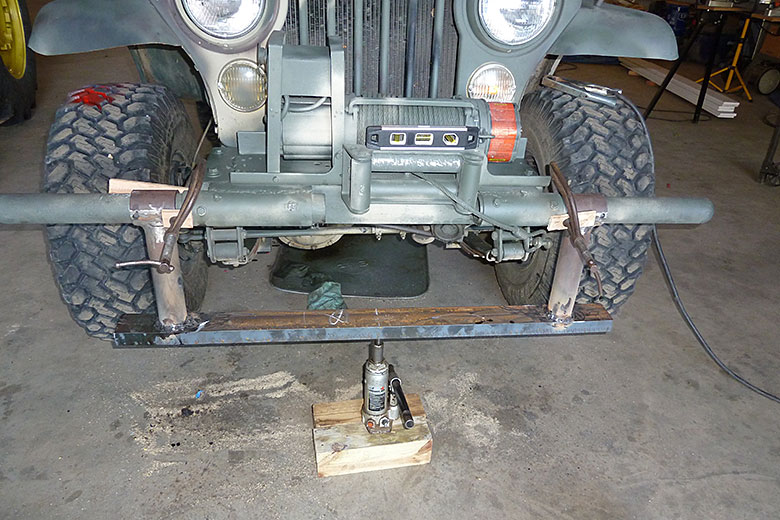
The front bumper and winch assembly were slipped onto the front frame rails. The frame was drilled as appropriate for two bolts on each top bumper side rail to pass vertically through the frame, as well as for two horizontal bolts to pass through the frame and side rails. 3/8” bolts were used to secure the assembly to the frame.
Two lengths of 2 3/8” drill tubing were cut for the bumper extensions. These two pieces of pipe slip into the 2 7/8” tubing welded to the front of the bumper and serve to protect the front wheels from impact high on the wheel radius that could damage ball joints. Both horizontal pipes are easily removable in the event tall obstacles and/or steep angles need to be climbed and of course for replacement if struck and bent. A pipe cap was welded on each bumper pipe. Weld on pipe caps are available at many pipe and steelyards, as well as welding supplies stores.
The end pieces of horizontal bumper tubing were fitted into the larger diameter tubing previously welded to the bumper assembly and existing holes were marked through the 2 7/8” mounts onto the 2 3/8” bumper tubing. Two holes in each of these horizontal end pieces were drilled and tapped to accept 3/8” bolts.
Next, two short sections of 2 7/8” pipe, two foot long lengths of 2 3/8” tubing, a four-foot length of three-inch “C” rail and a four foot, two-inch length of wooden 2×4 were cut. Radii cuts were made at one end of each piece of 2 3/8” tubing to accept the 2 7/8” collars and the two were then welded together.
Each collar was drilled for mounting bolts and slipped onto the 2 3/8” horizontal end pieces already attached to the bumper. The “C” rail was centered on the Jeep along with the one-foot lengths of 2 3/8” tubing and all parts were carefully aligned. A hydraulic jack was used to hold the aligned parts in tension for welding. The “C” rail was welded to the stubs of 2 3/8” tubing. A piece of ½” rebar was bent into a “U” shape and welded onto the “C” rail for the winch cable hook.
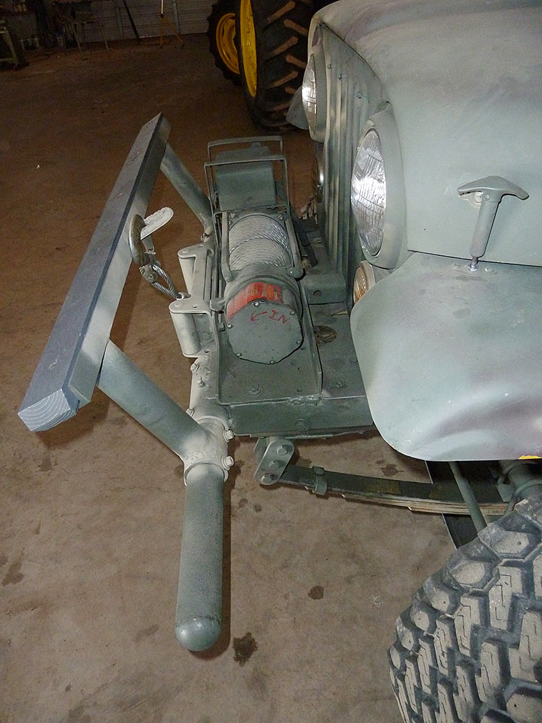
The pusher bar assembly was then rotated into a horizontal position on the 2 3/8” bumper end pieces and holes in the short 2 7/8” tubing were marked on the end pieces for drilling. The bar was then raised 45 degrees and holes were remarked and drilled.
Two 3/8″ x 3″ bolts, lock washers and nuts secured the pusher bumper in either horizontal or 45 degree upright position. The latter position was chosen so that if a deer or other large animal were struck, it would be forced down and not over the hood. With the pusher bar in this position, the headlights and park lamps are visible from the front. A length of 2×4 was beveled and mated to the pusher bar “C” rail and bolted in place using five ¼” x 2” carriage bolts.
Wiring
The winch controller included about four feet of wire for connection to the battery, which was too short for this application. This wiring was removed from the contactor/controller solenoids and replaced by two longer lengths of surplus 4 gauge cable left over from electrode wiring on an arc welder. Two copper lug mounts for 5/16” bolts were crimped and soldered onto one end of each wire for connection to the contactor/controller solenoids. Larger diameter wiring was chosen for this project to minimize I2R losses associated with the long run of wire required to connect the winch to the battery.
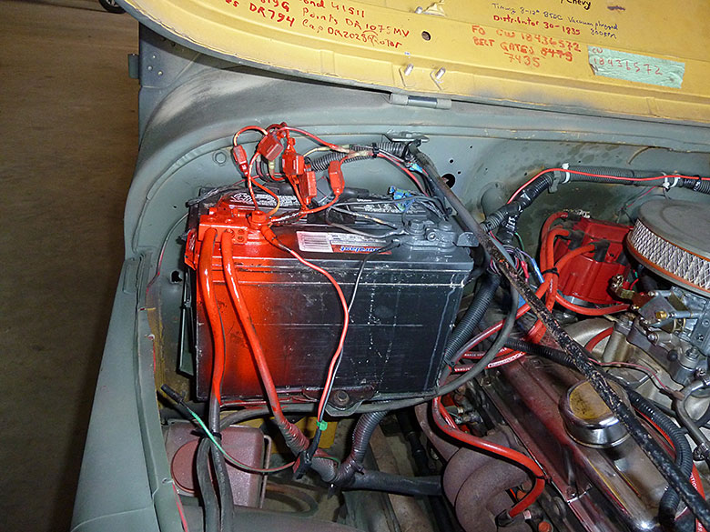
Aftermarket battery terminal connectors manufactured to accept two four gauge wires (positive terminal wires route to the starting motor and one to the winch; negative terminal wires route to vehicle ground and other to winch) replaced the existing single wire battery terminals. These connectors were purchased from AutoZone, however, the connector used was not located in their online catalog. For reference, the terminal connectors used are similar to that found in the following link.
From the positive terminal, the heavy cables running to the starting motor solenoid and to the winch contactor/solenoids are easily visible. The smaller gauge wires and fuse assemblies on each terminal connector are for radio harnesses. The positive and negative winch cables were carefully routed under the vehicle and up near the rear of the radiator and along the fender to the battery. These cables were secured to the fender by use of ½” one-hole conduit straps.
A separate project involved fabricating an extended length starting battery tray for this Jeep in order to accommodate a larger cranking capacity deep cycle battery. Deep cycle batteries are designed to be almost completely discharged without damage and are useful when operating both radio transmitters and winches.
Recovery Kit
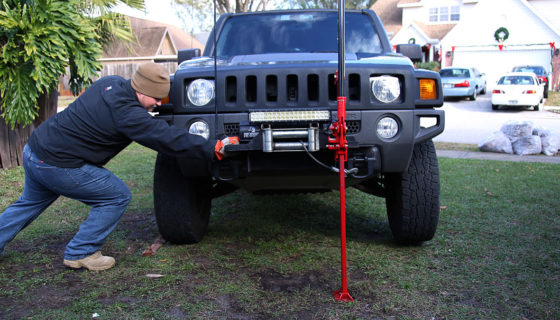
No vehicle with a winch is complete without a recovery kit. On the back bumper of this Jeep (not seen) is a mount for a full-size tire, 100 feet of 3/8” wire cable wound inside of the spare wheel well where it contacts the mount, a short shovel and HiLift Jack. A long handle single bit axe is affixed inside the right side passenger front seat area and there’s a high capacity 12v air compressor mounted to brackets under the hood.
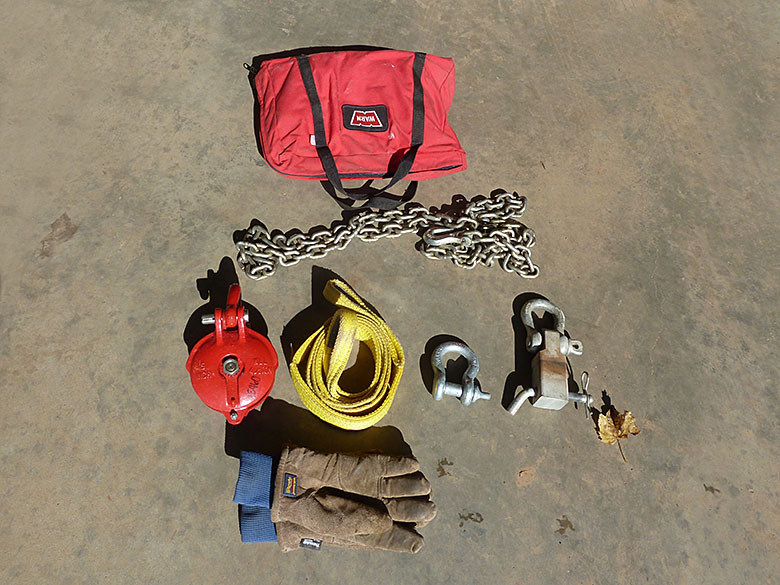
A Warn recovery kit is also carried which includes a short length of heavy duty chain and hooks, a tree strap (used to prevent damage to tree bark when a tree is used as an anchor point), gloves, two shackles, a pair of heavy leather gloves and a special low friction cable pulley designed to be opened for easy cable/cable hook routing
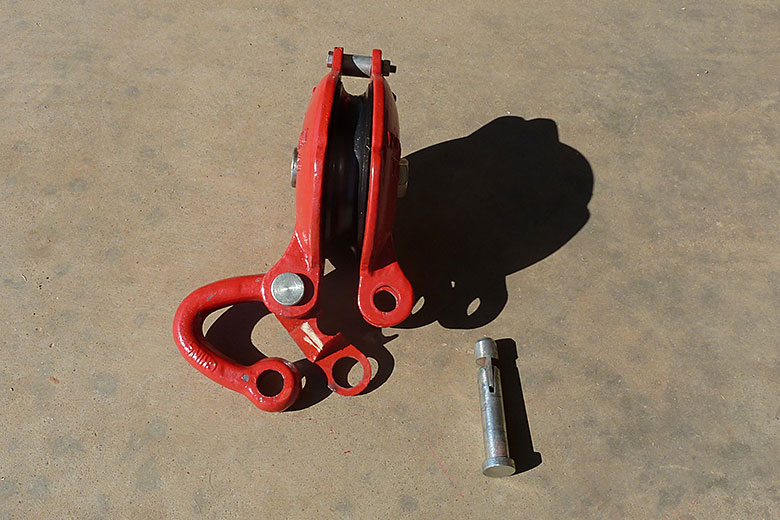
When used as a single pulley, off-axis pulling is possible. However, when used as a traveling or moveable pulley (winch line passes through pulley and back to the vehicle) connected to an anchor point, it doubles the pulling capacity of the winch.
Future Projects and Conclusion
Sometime in the future, I may add a cable cutter fabricated out of a worn road grader blade to the front of the jeep and may add expanded metal mesh between the pusher bar rails. With the pusher bar in the horizontal position, the metal mesh would allow me to carry some lightweight bulky materials.
Whenever I get a Jeep really stuck in a hard place I hear my father saying, “Son, son, all that thing is good for is to take you somewhere you have no business going in the first place.”
Hopefully, you’ll never have to use a winch and recovery kit in a serious survival situation. If you do, however, a robust bumper and large capacity winch will help get you through that hard place.
Questions and comments are most invited.
Editor-in-Chief’s Note: Steve V., The Panhandle Rancher, is retired from an intelligence organization that took him around the globe from pole to pole. He’s peered into a cradle of mankind at Olduvai Gorge, landed ski planes on Swiss Alps near La Dame Blanc, hunted dangerous game in Africa and walked with curiosity all of his life.

Discussion